Capabilities and Features of the RCSWin Software
Below is a brief summary of some of the main features of the RCS software. Browse through each of the sections within this page to view additional details and specifics on the various items mentioned below.
- Mechanical design calculations per ASME Section VIII Division 1 and TEMA for all major components, including cylinders and tubes, heads, cones, nozzles and nozzle reinforcement, flanges, floating heads, UHX tubesheet calculations, supports, exchanger weights, center of gravity, and numerous other details.
- Tube layout program
- Interactive graphical editor that allows users to move and relocate various components on their design.
- A full scale 3D graphical model of the exchanger, both as a solid (external) model, and a complete 3D internal model.
- Ability to generate a complete set of detail drawings for fabrication of each exchanger, which can be exported to any CADD program
- Bill of Material program that can build a complete BOM off of each design.
- Estimating program that is extremely detailed and customizable, which generates both estimated costs, and estimated hours for any given design.
- Graphical input screens for flanges and floating heads that allow the user to pictorially specify each dimension. Very useful for matching existing geometry on a duplicate exchanger.
- Inquiry and Purchase Order programs that can build inquiries and POs off of BOMs from any design. Parts from multiple designs can be combined into a single inquiry or PO.
- CNC drill file creation from any tube layout. CNC drill files can be customized and templates can be set up to conform to various different drill formats.
- Access to material properties for any material defined within ASME Section II Part D, as well as the ability to manually enter physical properties for any material desired.
- Ability to select from a list of defined gasket types, or add any other type of gasket to your database, which can be kept and accessed as needed.
- Interface with HTRI. RCS can import data from an HTRI .DBO file and use this geometry as a basis for an RCS design. RCS can also link directly with HTRI using the HTRI automation server. This is a bi-directional interface that allows users to read from HTRI Xist files and write back to them as well. Note that this requires both an RCS and HTRI license to be present on the same machine.
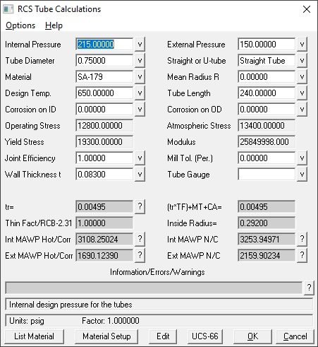
- Many of the calculations available for a full design are also available as standalone utilities, without having to specify an entire exchanger. This is a very useful feature for running calculations on parts and pieces, such as replacement shells or channels, or doing a quick check on the required thickness of a cylinder or tubes, etc.
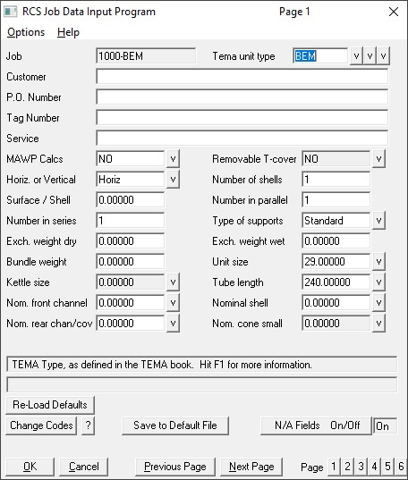
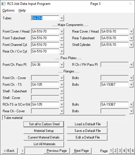
Each job begins with the data input process. RCSWin has a series of six pages of data input where the user specifies all of the basics about each design. This includes elements such as TEMA type, diameter, number of tubes, design conditions, materials, gaskets, and much more. This information is used as a starting point for the design process.
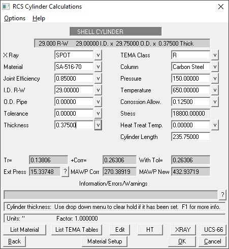
After the data input is complete, work can begin on the calculations. RCS starts with nailing down the boundary conditions for the exchanger, which includes tubes, cylinders, heads, and cones. These are the major components that must be set before further calculations such as flanges, floating head, tubesheets, etc. can be performed. RCS performs standard required thickness calculations for each of these components, as well as cone reinforcement calculations for internal and external pressure per appendices 1-5 and 1-8.
Nozzles
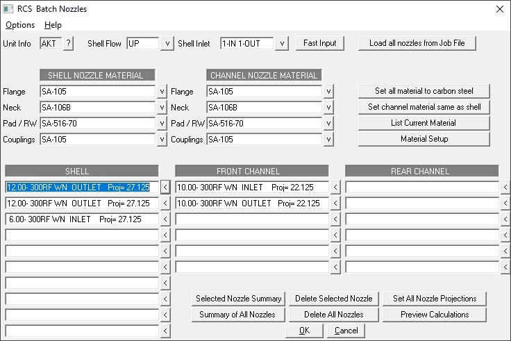
After the boundary conditions are established, the next step is adding nozzles to the design. Nozzles can be manually added, and this is the typical approach for auxiliary nozzles, but the preferred entry method for the main process nozzles is with the "Fast Input" feature. This option establishes the flow direction, number of inlet and outlet nozzles, and TEMA configuration to locate the nozzles. It will automatically offset nozzles if necessary, based on the number of tube passes. This feature ensures that process nozzles are located properly.
RCS can handle all types of nozzles: WN, slip on, LWN, stubs, and forged necks. In addition, reinforcement pads can be added as needed. Nozzles can have any desired projection, and can have elbows and reducers. RCS employs a series of algorithms to arrive at an appropriate nozzle design, first incrementing the nozzle thickness, then adding a pad, then increasing weld sizes, then moving up to a LWN, and lastly moving to a forged neck. Users can let RCS run this design logic, or manually select a particular type (for example, if the customer requires LWN nozzles). RCS will also select an appropriate nozzle flange rating, but this can also be manually changed by the user.
In addition to all of the standard nozzle calculations, RCS can also perform nozzle loadings per Werco Bulletin 107, and recently has added the ability to run UG-44(b) calculations for reduced equivalent pressure due to nozzle moments and loads. All of these calculations can be generated for any desired nozzle.
After the initial boundary components are set, RCS can begin designing the remainder of the exchanger. There are multiple steps involved in this process. The first is what RCS refers to as a "batch run", where RCS will go through a lengthy series of calculations to arrive at a preliminary design. For estimators, this process is often enough to arrive at a design that is suitable, but engineers will likely want to further customize their design by going into what RCS calls Menu Mode, and making additional changes to their design.
Batch Execution Process:
The batch execution process includes the following steps:
- Cover sheet data
- Design data summary
- Nozzle Reinforcement calculations
- Flange calculations (preliminary)
- Floating head calculations (preliminary)
- Tube layout calculations
- Bend schedule calculations
- ASME UHX tubesheet calculations
- Flange calculations (finalizing of flanges, using actual tubesheet thickness obtained via UHX in previous step)
- Floating head calculations (finalizing of floating head calculations after UHX)
- Tube calculations
- ASME B16.5 Pressure / Temperature rating calculations
- Exchanger dimensional analysis and calculations
- Bundle dimensions and calculations
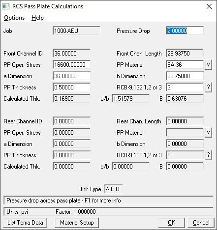
- Pass plate calculations
- Cone reinforcement for internal and external pressure (only run by default if this is a kettle type unit, but additional cones can be added to any design)
- Support calculations (preliminary). Both top and bottom support calculations are run if this is a stacked unit, otherwise just standard support calcs are run)
- Exchanger weights and center of gravity calculations
- Support calculations (finalizing, using calculated weights from previous step)
- Cover sheet data - updated with the finalized info from all steps above
If RCS is unable to obtain a suitable result in any of the above calculations, it will either halt execution or warn the user and proceed, depending on the severity of the problem. If no errors are encountered during this process, then the resulting exchanger is a complete design that is compliant with ASME and TEMA Codes and Standards. However, most engineers will want to further customize this design in a variety of different ways.
Design Customization:
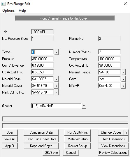
After the initial batch run is complete, the process of customizing the design can begin. Virtually all aspects of the design can be altered as needed, but common areas of interest are flanges, tubesheets, bundle geometry (baffle locations and spacing), and the tube layout. Below are some sample images of various calculation programs in RCS.
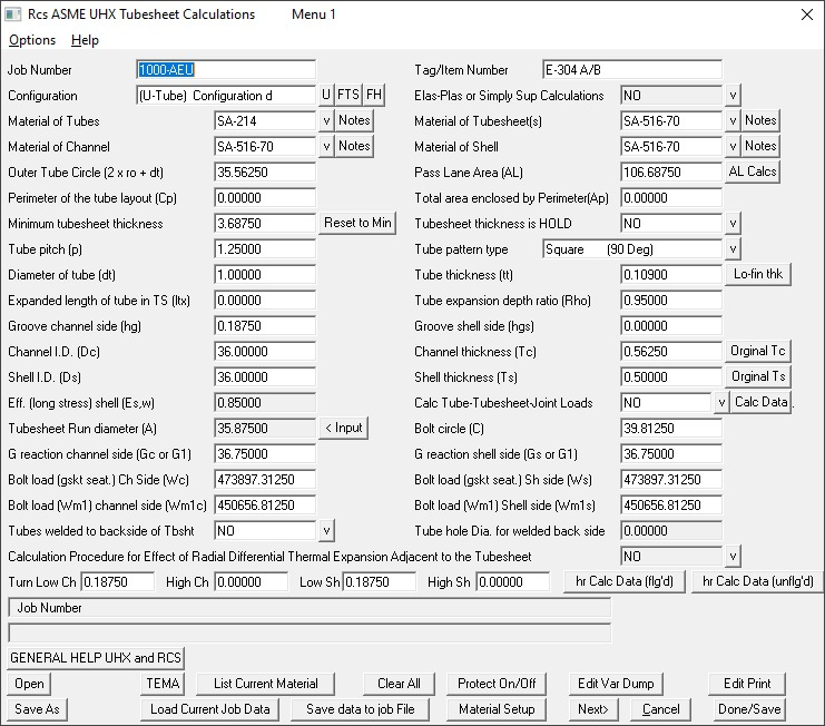
Note that there are actually multiple pages of data input for the UHX calculations, as this is the single most intensive set of calculations in ASME. The screen shot above is just a sample from one page.
Each set of calculations performed during the design process is retained and saved as part of the RCS Print File. This file can be viewed at any point during the design process. When calculations are complete, the entirety of the calculations can be printed, or any individual section can be printed at any point. Calculations can be displayed in both English and Metric units. In addition, RCS has the capability to edit the format files that generate these printouts, as well as editing the units used to generate the printouts. This gives an incredible level of detail and control to the printout generation. For example, in English units, length is displayed in inches, and in Metric units, length is in cm. If the user prefers to use mm for Metric printouts, they can alter the unit system so that all calculations will display mm instead of cm.
In addition, there are two different version of the printouts: The standard printout and the extensive printout. In the standard printout, input data is shown, then calculated variables and results are displayed in a relatively concise fashion. The extensive printout expands on the calculations and results, referring to Code paragraphs at times, and displaying formulas, etc. Again, both the standard and extensive formats are available in English or Metric units.
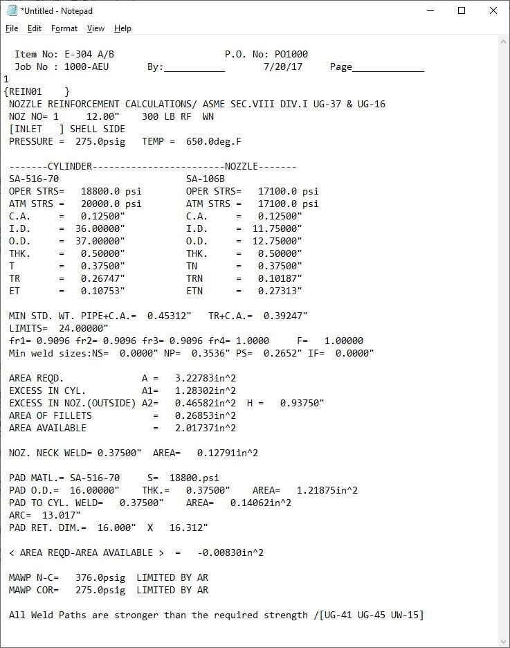
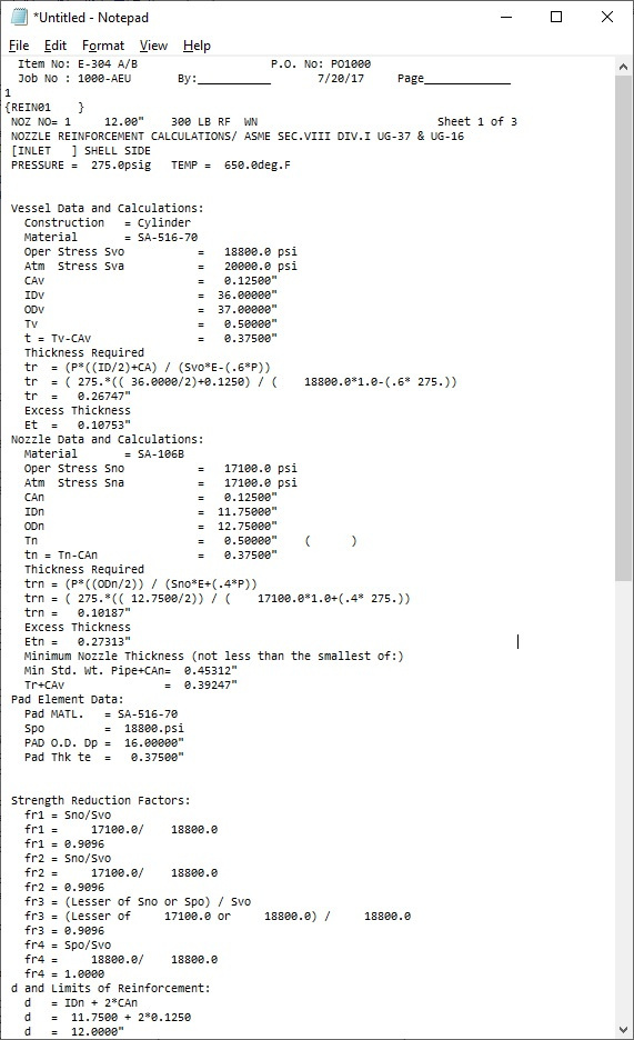
The screen captures show a typical nozzle reinforcement calculation printout in the standard format, and then a portion of the extensive format for comparison.
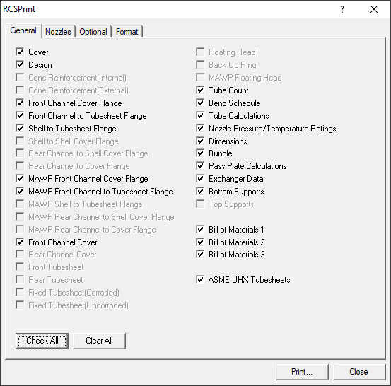
Lastly, any individual component from the print file can be printed independently of the others, or they can all be printed. This image shows some of the options available when printing calculations. Grayed out options are items that do not exist for this particular design.
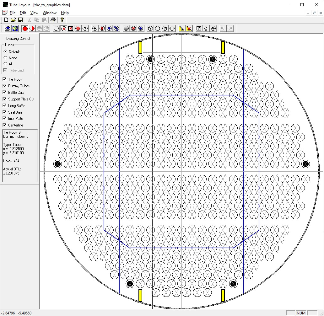
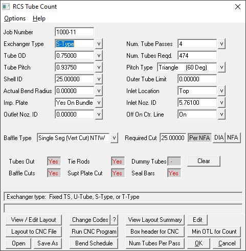
RCSWin has a variety of graphical tools to assist engineers in creating their mechanical designs. The most frequently accessed tool is the RCS Tube Layout program. This program is fully interactive, giving the designer complete control over the layout. One through twelve pass layouts can be generated and optimized automatically, including alternate tube pass arrangements. Exchangers containing up to 32 total tube passes can be generated, but the user must specify passlane locations and take a more hands on approach when designing these higher tubepass arrangements.
In addition to generating tube layouts, RCS also has a CNC drill program that will automatically generate drill files based off of the tube layout. These drill files can be generated in a variety of different formats for many different drill types, and manufacturers can create their own custom drill file format if none of the standard templates are compatible with their CNC drills.
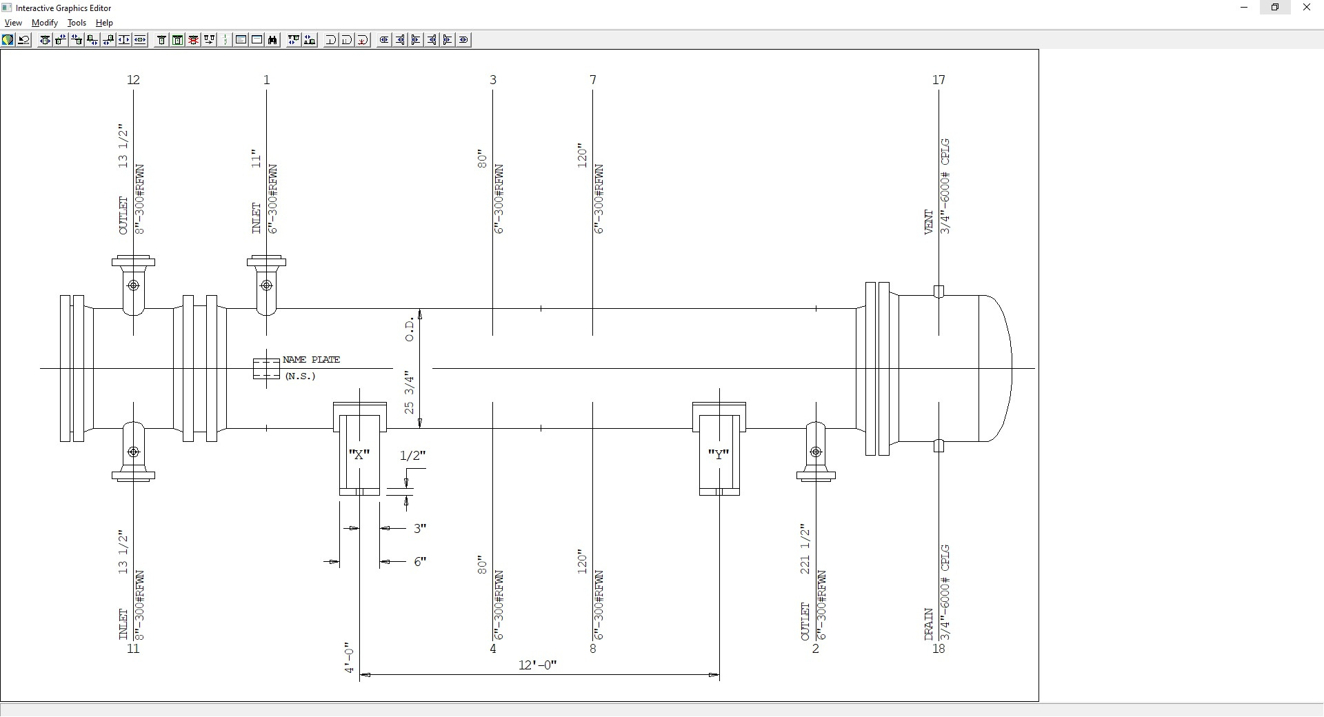
Another useful graphical tool is the Interactive Graphics Editor. This utility has a variety of features, but is primarily used to obtain a clean and accurate outline or setting plan drawing. The current exchanger is shown in a format similar to that appearing on a standard setting plan drawing. The user has the ability to pictorially arrange things, such as moving and duplicating nozzles, changing support locations, altering the length of the front and rear channels, etc.
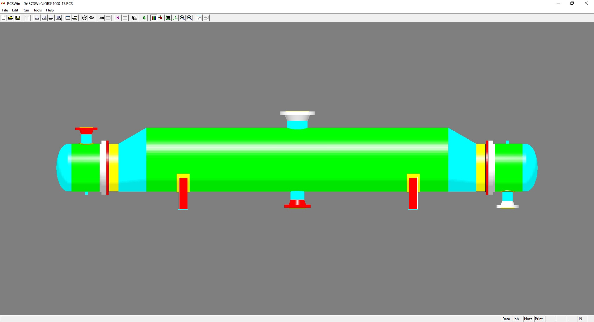
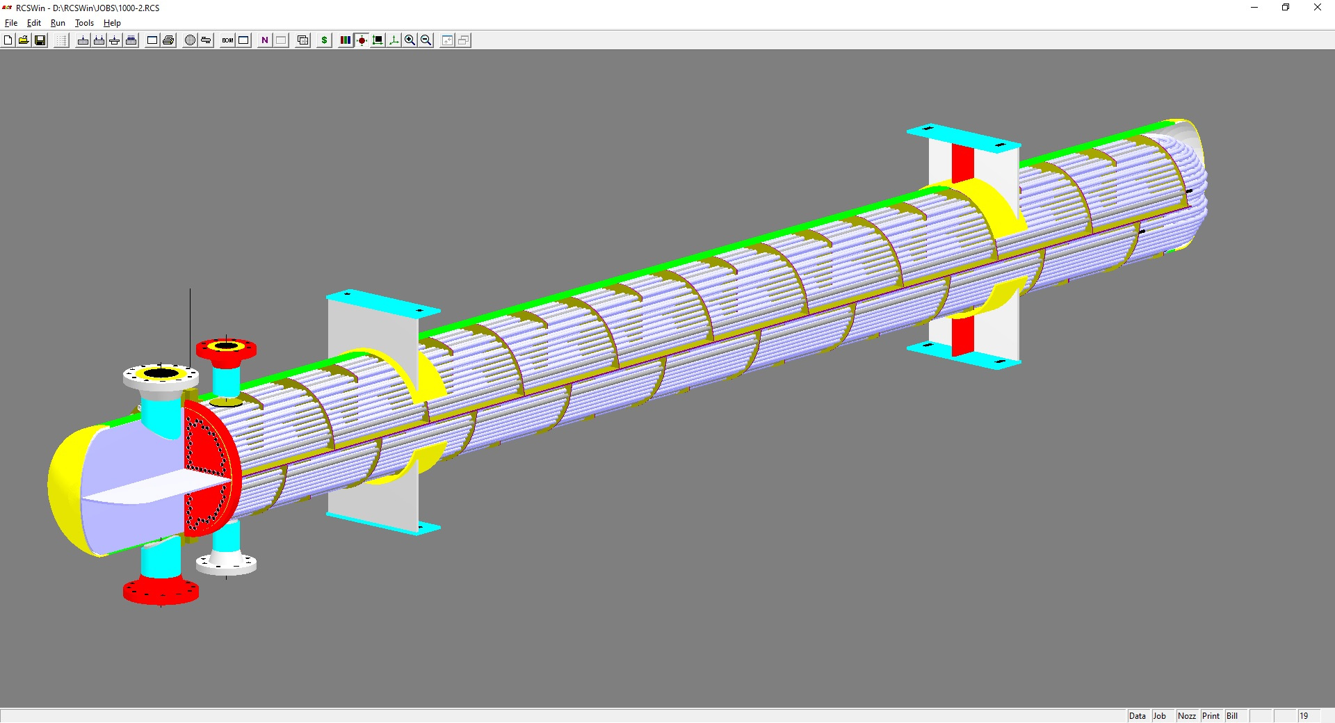
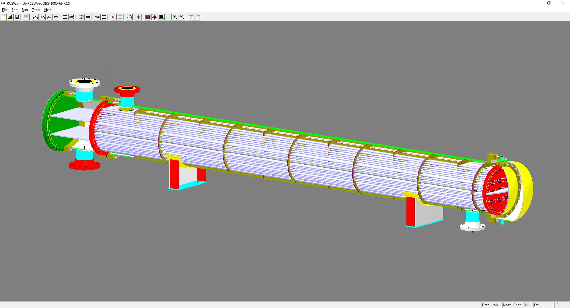
Perhaps the single most useful graphical tool within RCS is the 3D model. RCS generates a complete set of detail drawings, but they are not to scale. The 3D model, on the other hand, is 100% to scale, and is a very useful tool for double-checking any design for any potential problems with nozzle location, nozzle to nozzle interference, support locations, baffle spacing, or simple mistakes that were made during the design process. RCS can generate both an external or surface model, and an internal model complete with all exchanger components. In addition, users have the ability to pick and choose various components to view. One common example is to select all bundle components so that a complete removable bundle can be viewed by itself.
Example of a surface model of a BKM style kettle reboiler:
Example of a 3D internal model of a BFU unit with stacked supports. Note that the 3D model can be rotated, zoomed in and out and viewed from any angle. Also note that only the periphery tubes are drawn in this example, but all tubes can be shown, or none at all if preferred.
Example of an AES style exchanger:
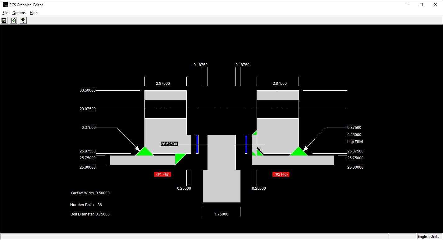
The final graphical tool available within RCS is a pair of graphical input screens for entering flange and floating head dimensions. This is a very handy tool for quickly specifying geometry, particularly in cases where a duplicate or replacement of an existing unit is desired. Rather than using an RCS designed flange or floating head, users can specify the exact geometry and RCS will simply calculate whether it is good or not. The flange input screen is shown below:
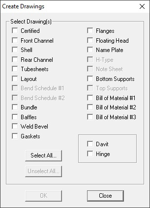
One of the main selling points of the RCS software is the ability to create a complete set of detail drawings for any design. This is particularly useful for fabricators and can be a tremendous time saver for their CADD department. All of the RCS drawings are available in two different formats: a native drawing format that can be viewed as a sketch directly within the RCS software, and as a DXF file, which can be opened directly within any CADD program. The drawings can be customized in several ways, such as changing from English to Metric units, changing how some of the dimensions are displayed, customizing of the title block, and a variety of other features. The image below shows a list of all of the drawings that can be generated within RCS, and the following images are samples of several of the different drawing types.
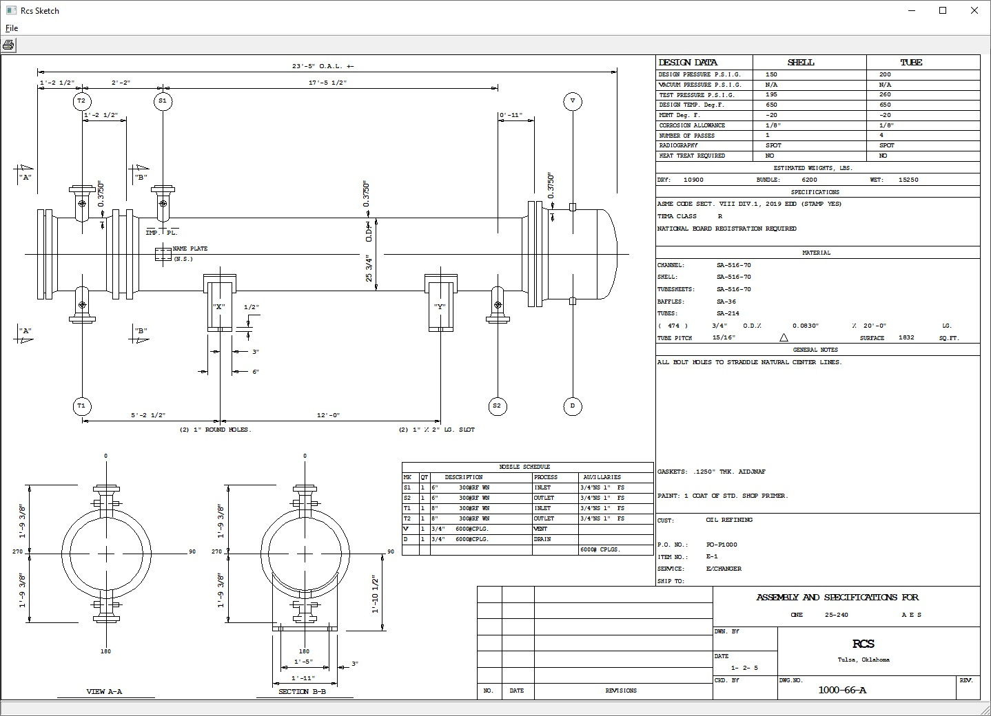
Sample Outline or Setting Plan drawing:
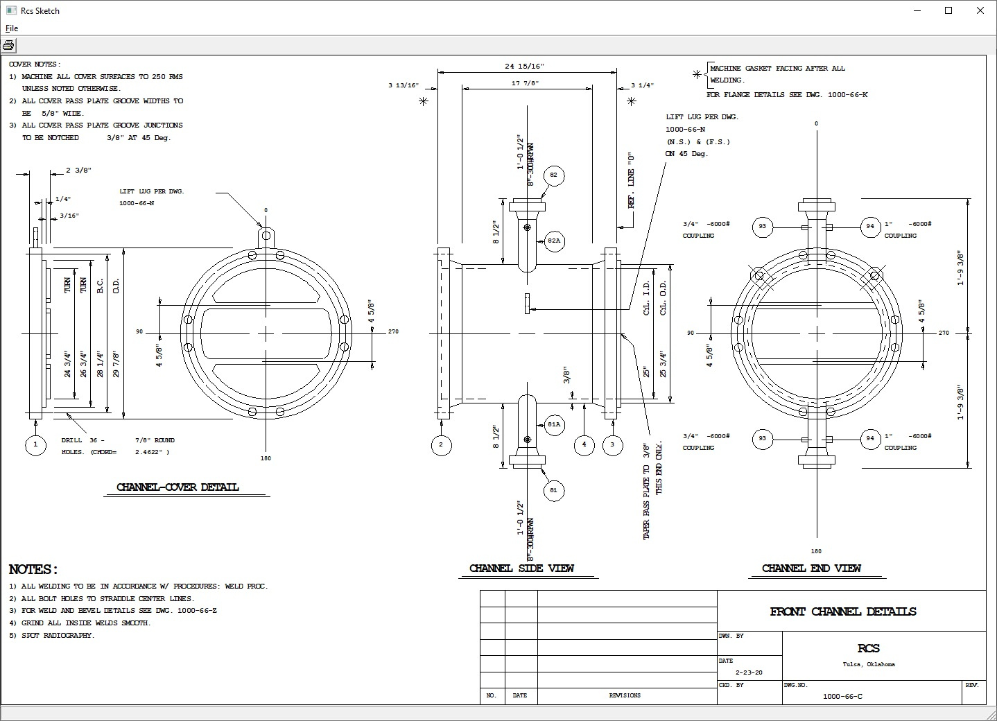
Sample Front Channel Drawing:
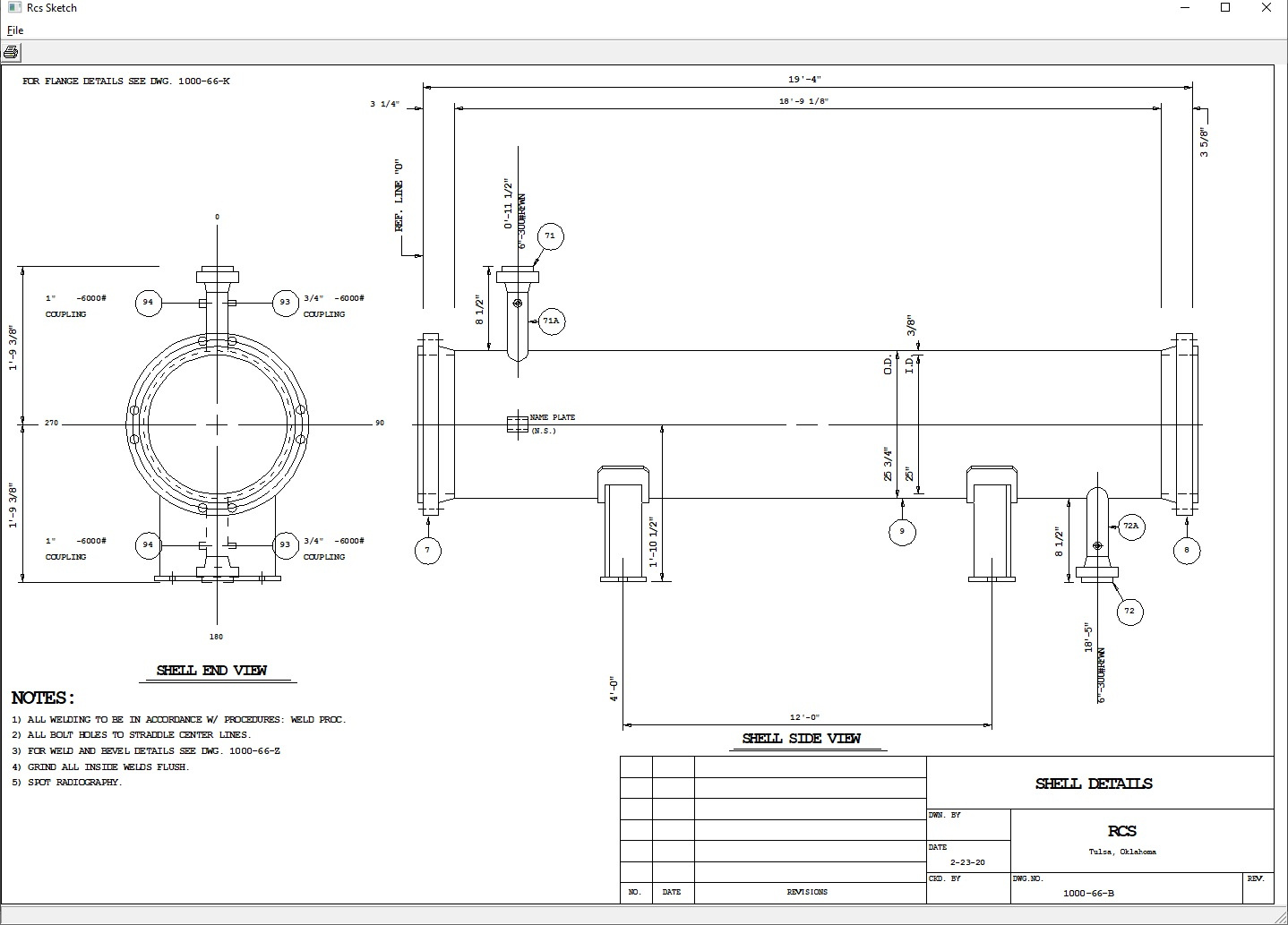
Sample Shell Drawing:
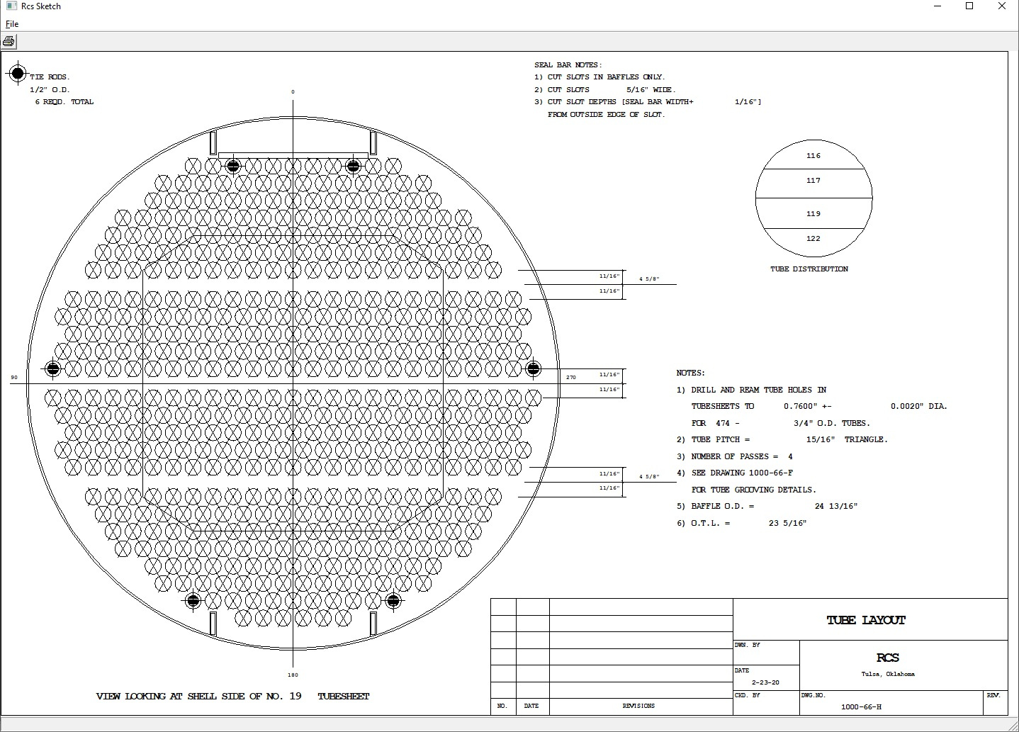
Sample Tube Layout Drawing:
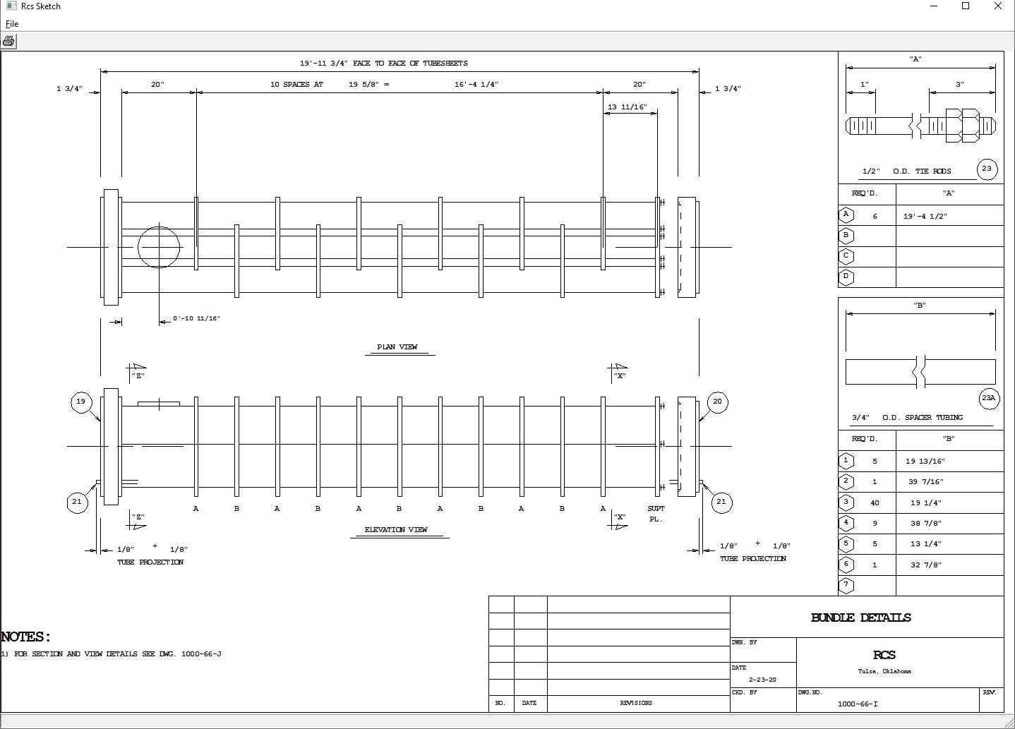
Sample Bundle Drawing:
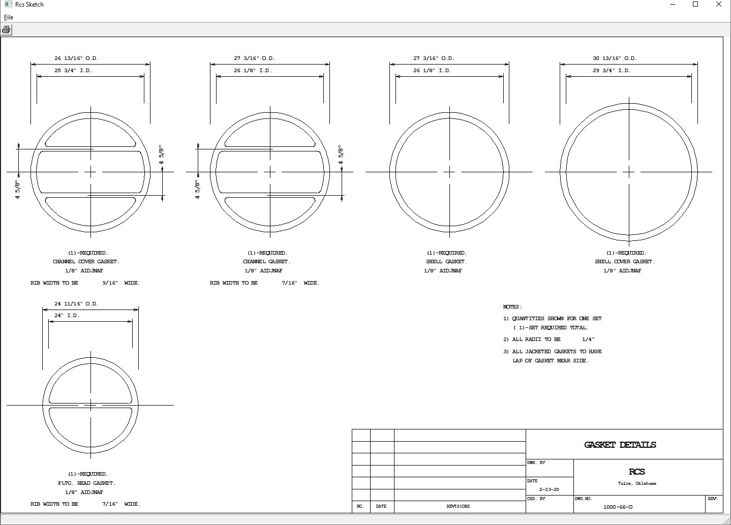
Sample Gasket Drawing:
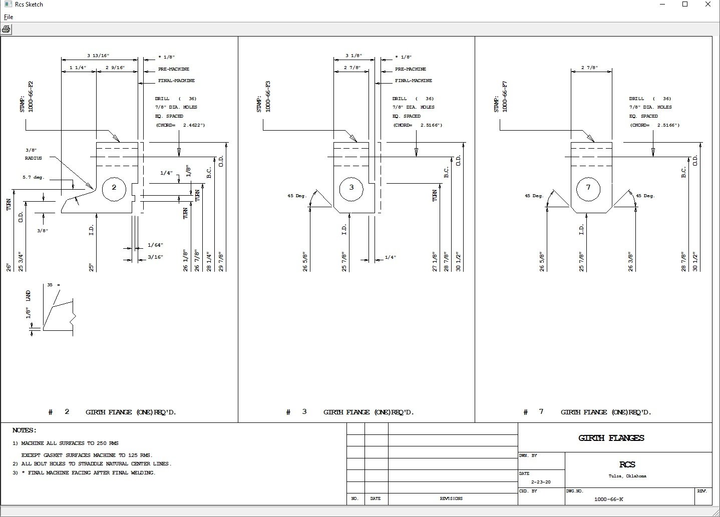
Sample Flange Drawing:
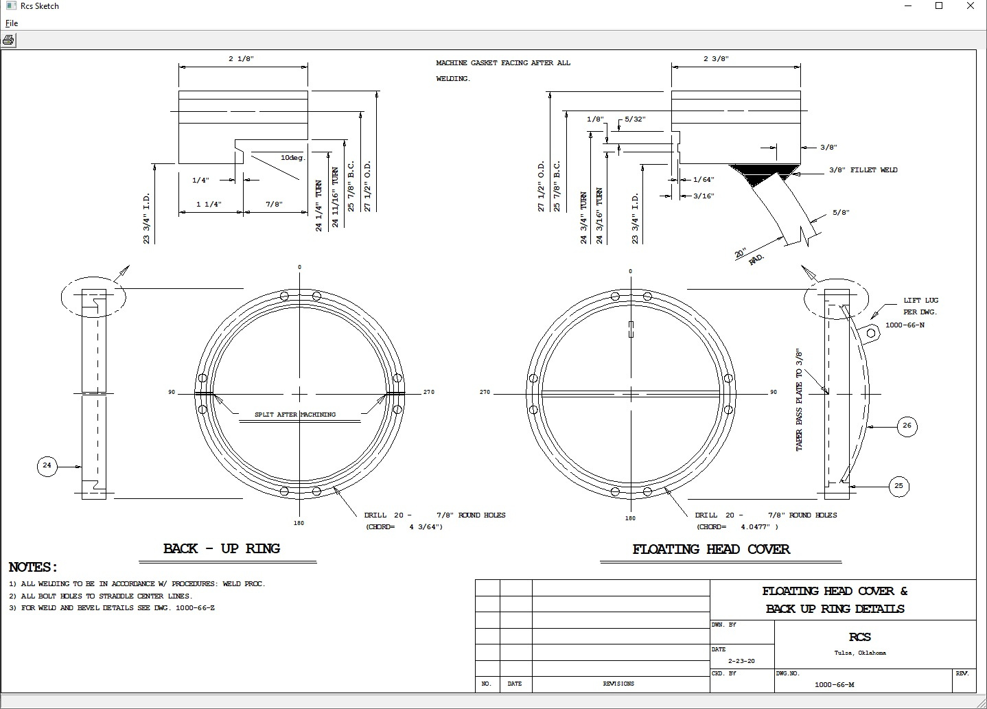
Sample Floating Head drawing:
In addition to the mechanical design and drawing generation, there are numerous other features within the RCSWin software:
- HTRI Interface:RCS has two different methods of interacting with HTRI. The first is via the HTRI .DBO file. HTRI has the ability to export data from an Xist shell and tube design to a .DBO file, and RCS can read this data in and use it as the basis for a new mechanical design. The second option is a bi-directional interface with HTRI's automation server. This allows the user to import data directly from an HTRI file and use it to create an RCSWin design. In addition, mechanical details from the RCS design can then be passed back to the HTRI file so that it can be rerun with the exactly geometry from the finalized design. Note that this interface requires both an HTRI and an RCS license on the same computer in order to function properly.
- Estimating ProgramRCS has an incredibly detailed and powerful estimating program. This program contains thousands of labor operations which incrementally break down every single portion of the fabrication process for each exchanger design. The estimating program will generate estimated weights, costs, and labor hours for an entire exchanger. This program requires a fair amount of customization in order to produce hours that are accurate for each specific fabrication shop's capabilities and processes, but can be an incredibly powerful tool to use for both cost estimates and shop loading. The program generates a variety of different reports, and has the ability to add virtually any cost associated with an exchanger, even outside contracted items, such as shipping costs, or contracting out hours for cylinder rolling, drilling, etc.
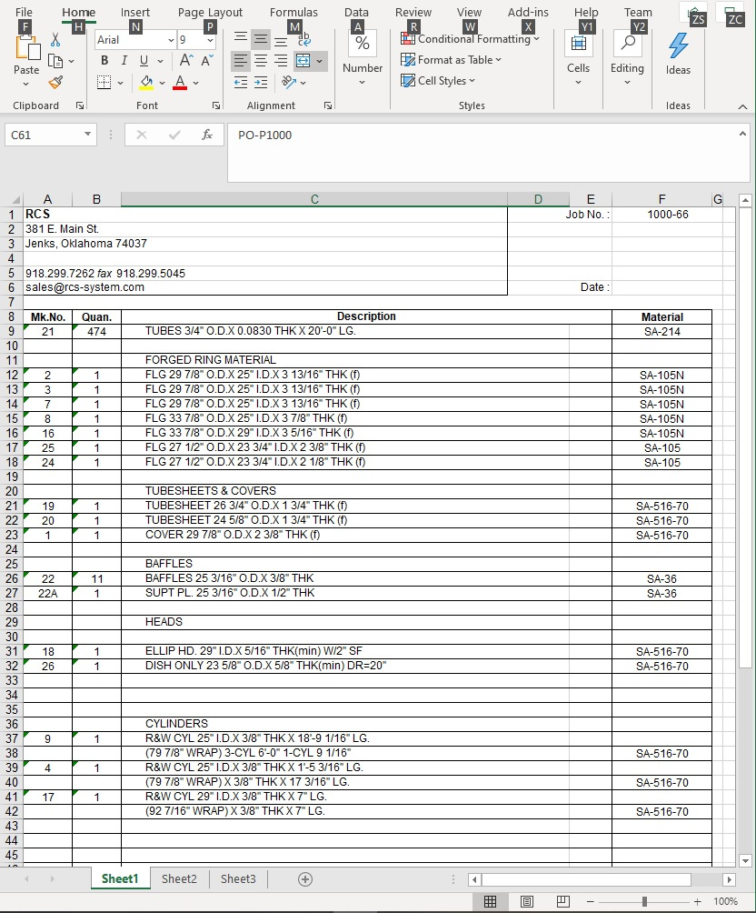
- Bill of Material ProgramThis program will generate a complete bill of materials for any exchanger designed within RCS. The BOM can be automatically generated, and can be edited manually within RCS. BOMs can be exported as DXFs to be edited within a CADD program, exported as Excel documents, or edited and printed directly within RCS as text files. Below is a sample page of the BOM exported to Excel:
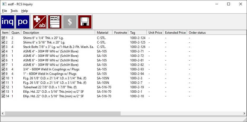
- Inquiry and Purchase Order ProgramsThe inquiry and purchase order programs build off of the Bill of Materials. Inquiries and Purchase Orders can be built for any RCS jobs that have had the BOM generated. Inquiries and Purchase Orders can pull from multiple jobs. Each company maintains their own vendor database, and the appropriate vendor can be selected for each Inquiry or Purchase Order. Items can be added to an Inquiry or Purchase Order by a few different methods: Their bill tag (this tag can be edited within RCS), material type or grade, or by part number. In addition, a keyword search option is available to select specific parts. A small sample inquiry is shown below:
- Quick calculations for virtually all exchanger componentsRCS has standalone utility programs for running calculations on tubes, cylinders, heads, cones, nozzle reinforcement, UHX tubesheet calculations, nozzle loadings, and a variety of other quick calculations. Note that all of these calculations can be run as part of a full exchanger design, but the standalone utility programs are a handy way to run a quick calculation without having to enter a full design. If these supplemental calculations are run while an active job is open, the user is given the choice to insert these calculations into their main print file so they can be retained as part of the job.
- Davit and Hinge Modules
Modules for creating davit and hinge DXF drawings for export to CADD programs.
- Kopp and Sayre
Kopp and Sayre method for calculation of expansion joints. This can be run both as a standalone utility program, or from within the UHX tubesheet design of an active job. - L.P. Zick Analysis
L.P. Zick method for analysis of horizontal saddles. This can also be run both as a standalone utility or as part of an active job. - Rib Length Calculator
- RCS Modules for trigonometry, weight, volume, and surface calculations
- Slope Program
This program calculates nozzle projections, dimensions, etc. for exchangers that are on a slope. - CNC Program
This program generates a CNC drill file for drilling tubesheets based off of any tube layout that is created.
- Cone Layout Program
This is actually a pair of programs. The first generates the necessary data to create a cone from a flat plate, dimensions, etc. and stores it in a file. The second program is an AutoLISP routine run withing AutoCAD that reads this file and generates a drawing.
- Section II Part D Materials
RCS gives access to all ASME Section II Part D materials for use in all calculations, and also includes the ability to add other materials manually that are not defined in ASME. - UG-44(b) Nozzle Flange Reduced Equivalent Pressure Calculations
Again, these can be run as part of a job or as standalone calculations. - PCC-1 Appendix O Bolting / Gasket Assembly Stress Calculations
These calculations are an optional addition to the standard flange calculations, and are run from within the flange design program.
 Click to edit
Contact Information:
Mailing Address:
RCS, Inc.
PO Box 417
Jenks, OK 74037
Phone:
918-299-7262
Email:
For technical support, software related questions, updates, etc.: support@rcs-system.com
For billing, pricing, and other sales related questions: sales@rcs-system.com